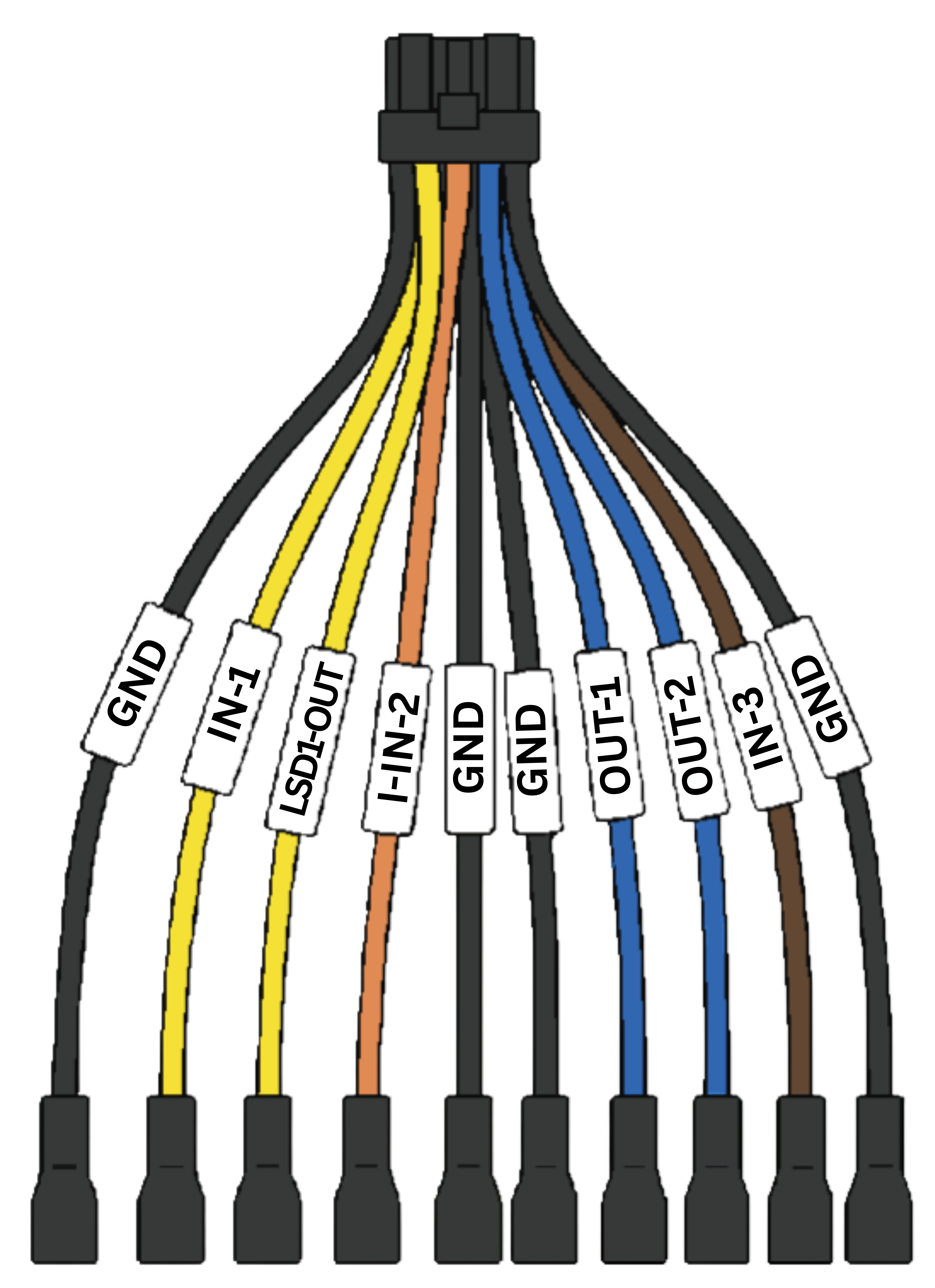
Use this workflow to connect the Auxiliary Cable (HCA-ACC1-01) to the LytxOne Gateway (LX1-G) in addition to your primary connection cable. This accessory adds ignition detection, power (PTO) detection, or both, expanding the Gateway with 10 additional input, output, and ground lines.
What You Will Need
- LytxOne Gateway (already connected using its primary cable)
- Auxiliary Cable (HCA-ACC1-01)
HCA-ACC1-01 Cable Components
| Wire |
Function |
Pin |
| IN-1 (Yellow) |
General-purpose input, for PTOs, switches, or push buttons |
2 |
| I-IN-2 (Orange) |
Dedicated ignition input, for engine ON/OFF detection |
4 |
| IN-3 (Brown) |
Secondary input for auxiliary devices or sensors |
9 |
| LSD1-OUT (Yellow) |
Low-side output, for controlling small loads or relays |
- |
| OUT-1 / OUT-2 (Blue) |
Configurable outputs for future or optional functions |
- |
| GND (Black) |
Ground, four lines for stable and flexible grounding |
1, 5, 6, 10 |
Connect the Cable
- With the engine off, connect the Auxiliary Cable's 10-pin connector to the I/O Expansion Port on the LytxOne Gateway.
-
Wire the input lines you need, based on your use case.
- Connect the appropriate ground wire (Black, pins 1, 5, 6, or 10) to a clean, unpainted metal bolt or chassis ground point.
- Confirm the cable is clear of the vehicle's pedals, steering linkage, and other moving parts. Physically operate all pedals through their full range of motion to check.
Wiring for Ignition Detection
The I-IN-2 (Orange) wire monitors voltage from a circuit powered only when the key is in the ON position. LOW (no voltage) means ignition off, HIGH (9 to 24V) means ignition on. This enables automatic trip start and stop based on ignition status, and improves the accuracy of events tied to ignition.
Wiring for Power (PTO) Detection
Connect IN-1 (Yellow) or IN-3 (Brown) to a power or signal line on the equipment you want to monitor. LOW means no voltage detected, HIGH (9 to 24V) means the line is active. When the input goes HIGH, the Gateway logs a Digital In 1 or Digital In 3 event, which can include video or image attachments.
The examples below are common use cases, not an exhaustive list, IN-1 and IN-3 can be wired to any equipment or switch that provides a HIGH or LOW signal, depending on what your fleet needs to monitor.
- PTO activation
- Door or hatch open/close detection
- Auxiliary lights or siren activation
- Tow, winch, or spreader operation
- Refrigeration or pump system monitoring
Wiring for a Push Button
Connect IN-1 (Yellow) or IN-3 (Brown) to a momentary push button, mounted separately from the Gateway or Camera, so the driver can manually flag an event on demand. When the button is pressed and the input goes HIGH, the Gateway logs a Digital In 1 or Digital In 3 event, which can include video or image attachments.
To finish the installation, continue to Step 3: Mount & Wire to secure the Gateway and mount the Camera, then Step 4: Activate, Verify, Complete to activate and verify the installation.
Safety Notice
Before installing or operating this device, read the full Safety and Maintenance Guidelines.